Self-balancing robot using Arduino
I wanted to learn more about electronics and programming so a friend suggested that I take on a project to see if I actually like doing the work.
I came across this video on Youtube and wanted to build it for myself.
I must state that I had no experience in electronics and programming outside of Mechanical Engineering degree curriculum.
This project was heavily inspired by YABR by Brokking. I am using slightly different hardware and as a result I had to revise his code to get it to work.
This project took a long time to complete (10 months) as I had underestimated its complexity. On the way, I had to stop and learn about how microcontrollers work, what are their computational limitations, how to program in C programming language, burnt components, hours and hours of testing PID coefficients, and so on.
Construction

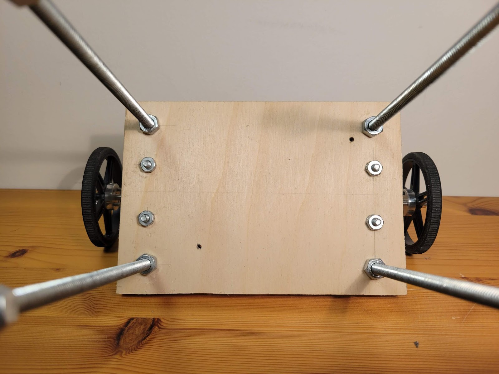
The physical design of the robot consists of two sheets of plywood and four holes at corners. Initial design used acrylic sheets but they were prone to vibrations and were noisy. Wood absorbs vibrations better.
I used ¼” threaded rods for the frame and the motors are mounted on the bottom shelf using L shaped brackets bought from Home Depot.
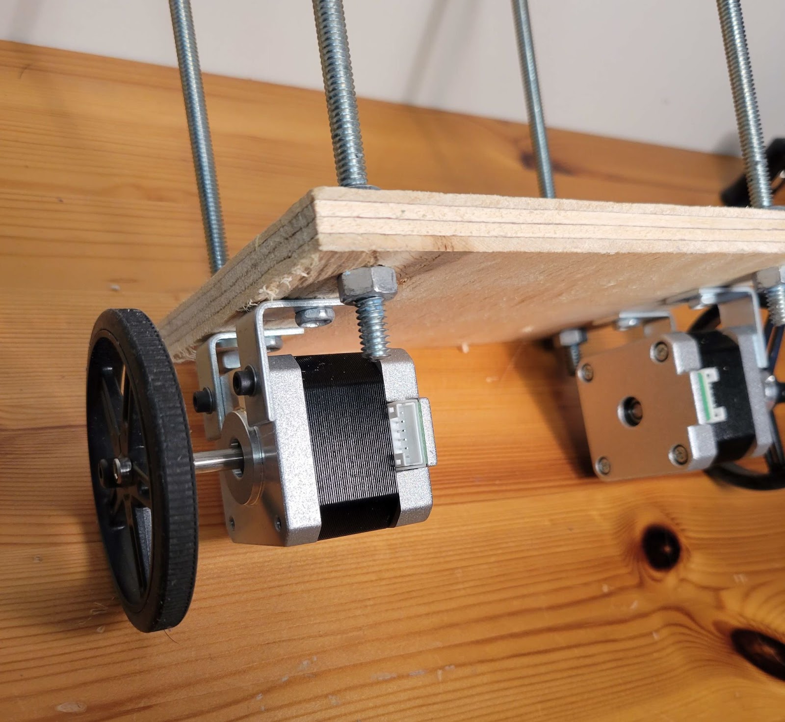

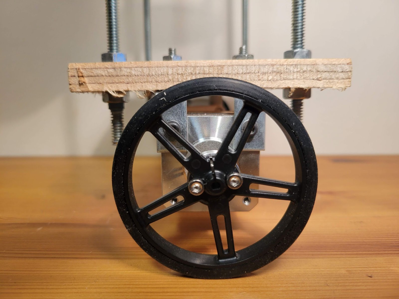
The motor shaft is 5mm in diameter with a flat and I used an off-the-shelf hub which mounts on it using a set screw. Then, wheels were mounted on the hub using two #4-40 screws.

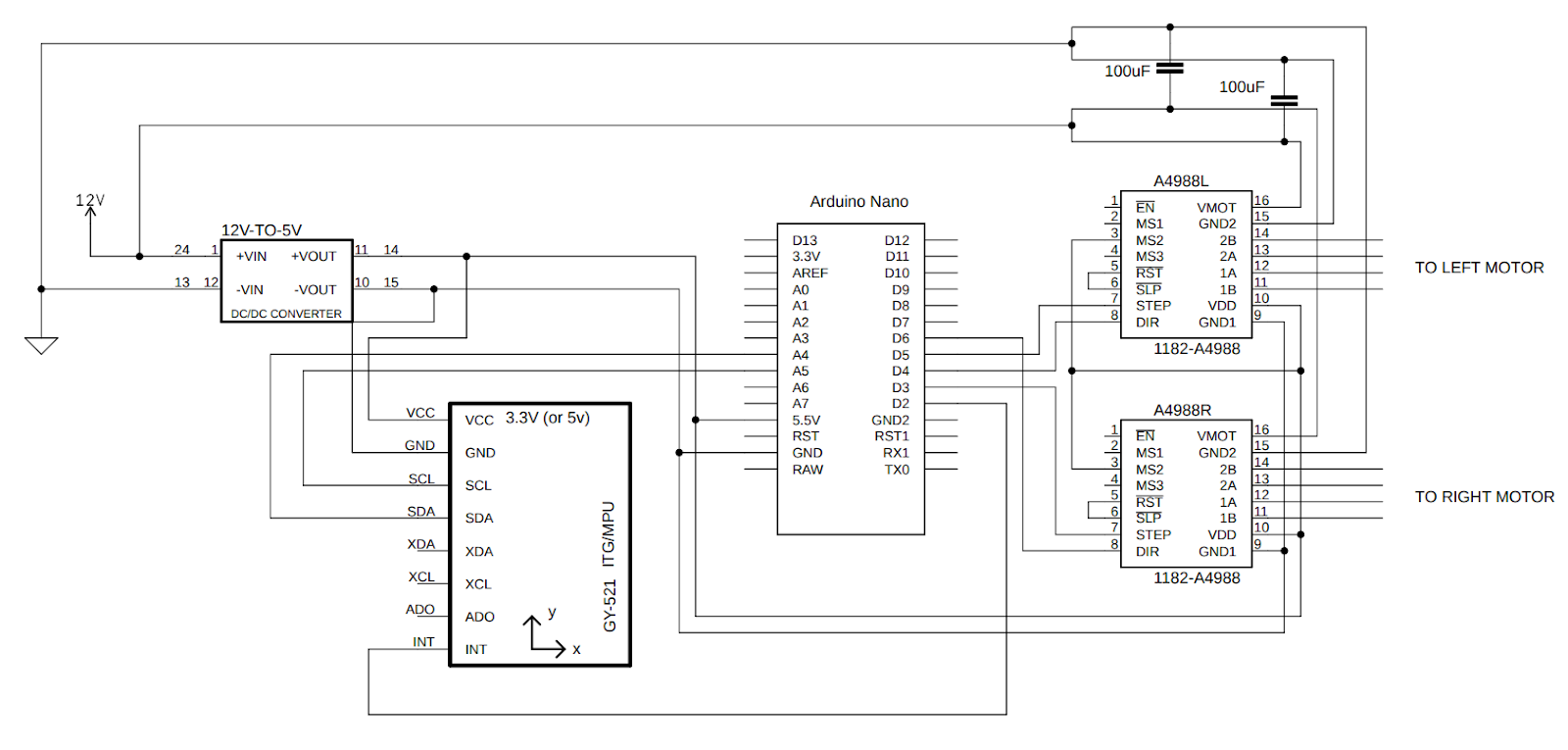
I soldered all the components on a DOT PCB. Initially, I used a breadboard for this purpose but the contact between the breadboard holes and the wires was not stable enough due to vibrations.
- The following components can be seen in the picture:
- Arduino Nano
- MPU6050 Gyro sensor
- 2x A4988 stepper motor drivers
- DC-DC voltage converter (this was added later, that’s why it is sticking out)
- 2x 100uF capacitors
Working
The robot is in equilibrium when it is upright. As it tilts in either direction, the motors move the wheels in the same direction to keep the balance.
The gyro sensor outputs the three linear and three angular acceleration components which are filtered and combined to calculate the angle of inclination.
This angle is the ‘error’ that is fed to the PID loop.
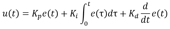
u(t) is the output of the PID loop Kp, Ki, and Kd are proportional, integral, and derivative coefficients.
The value of u(t) is what drives the motors to achieve the required balance.
The arduino code can be found in the github repository here
Code
///////////////////////////////////////////////////////////////////////////////////////
//Terms of use
///////////////////////////////////////////////////////////////////////////////////////
//THE SOFTWARE IS PROVIDED "AS IS", WITHOUT WARRANTY OF ANY KIND, EXPRESS OR
//IMPLIED, INCLUDING BUT NOT LIMITED TO THE WARRANTIES OF MERCHANTABILITY,
//FITNESS FOR A PARTICULAR PURPOSE AND NONINFRINGEMENT. IN NO EVENT SHALL THE
//AUTHORS OR COPYRIGHT HOLDERS BE LIABLE FOR ANY CLAIM, DAMAGES OR OTHER
//LIABILITY, WHETHER IN AN ACTION OF CONTRACT, TORT OR OTHERWISE, ARISING FROM,
//OUT OF OR IN CONNECTION WITH THE SOFTWARE OR THE USE OR OTHER DEALINGS IN
//THE SOFTWARE.
///////////////////////////////////////////////////////////////////////////////////////

#include <Wire.h>                                            //Include the Wire.h library so we can communicate with the gyro

int gyro_address = 0x68;                                     //MPU-6050 I2C address (0x68 or 0x69)
int acc_calibration_value = -323;                            //Enter the accelerometer calibration value

//Various settings
float pid_p_gain = 15;                                       //Gain setting for the P-controller (15)
float pid_i_gain = 1.5;                                      //Gain setting for the I-controller (1.5)
float pid_d_gain = 30;                                       //Gain setting for the D-controller (30)
float turning_speed = 30;                                    //Turning speed (20)
float max_target_speed = 150;                                //Max target speed (100)

///////////////////////////////////////////////////////////////////////////////////////////////////////////////////////////////////////
//Declaring global variables
///////////////////////////////////////////////////////////////////////////////////////////////////////////////////////////////////////
byte start, received_byte, low_bat;

int left_motor, throttle_left_motor, throttle_counter_left_motor, throttle_left_motor_memory;
int right_motor, throttle_right_motor, throttle_counter_right_motor, throttle_right_motor_memory;
int battery_voltage;
int receive_counter;
int gyro_pitch_data_raw, gyro_yaw_data_raw, accelerometer_data_raw;

long gyro_yaw_calibration_value, gyro_pitch_calibration_value;

unsigned long loop_timer;

float angle_gyro, angle_acc, angle, self_balance_pid_setpoint;
float pid_error_temp, pid_i_mem, pid_setpoint, gyro_input, pid_output, pid_last_d_error;
float pid_output_left, pid_output_right;

///////////////////////////////////////////////////////////////////////////////////////////////////////////////////////////////////////
//Setup basic functions
///////////////////////////////////////////////////////////////////////////////////////////////////////////////////////////////////////
void setup(){
  Serial.begin(9600);                                                       //Start the serial port at 9600 kbps
  Wire.begin();                                                             //Start the I2C bus as master
  TWBR = 12;                                                                //Set the I2C clock speed to 400kHz

  //To create a variable pulse for controlling the stepper motors a timer is created that will execute a piece of code (subroutine) every 20us
  //This subroutine is called TIMER2_COMPA_vect
  TCCR2A = 0;                                                               //Make sure that the TCCR2A register is set to zero
  TCCR2B = 0;                                                               //Make sure that the TCCR2A register is set to zero
  TIMSK2 |= (1 << OCIE2A);                                                  //Set the interupt enable bit OCIE2A in the TIMSK2 register
  TCCR2B |= (1 << CS21);                                                    //Set the CS21 bit in the TCCRB register to set the prescaler to 8
  OCR2A = 39;                                                               //The compare register is set to 39 => 20us / (1s / (16.000.000MHz / 8)) - 1
  TCCR2A |= (1 << WGM21);                                                   //Set counter 2 to CTC (clear timer on compare) mode

  //By default the MPU-6050 sleeps. So we have to wake it up.
  Wire.beginTransmission(gyro_address);                                     //Start communication with the address found during search.
  Wire.write(0x6B);                                                         //We want to write to the PWR_MGMT_1 register (6B hex)
  Wire.write(0x00);                                                         //Set the register bits as 00000000 to activate the gyro
  Wire.endTransmission();                                                   //End the transmission with the gyro.
  //Set the full scale of the gyro to +/- 250 degrees per second
  Wire.beginTransmission(gyro_address);                                     //Start communication with the address found during search.
  Wire.write(0x1B);                                                         //We want to write to the GYRO_CONFIG register (1B hex)
  Wire.write(0x00);                                                         //Set the register bits as 00000000 (250dps full scale)
  Wire.endTransmission();                                                   //End the transmission with the gyro
  //Set the full scale of the accelerometer to +/- 4g.
  Wire.beginTransmission(gyro_address);                                     //Start communication with the address found during search.
  Wire.write(0x1C);                                                         //We want to write to the ACCEL_CONFIG register (1A hex)
  Wire.write(0x08);                                                         //Set the register bits as 00001000 (+/- 4g full scale range)
  Wire.endTransmission();                                                   //End the transmission with the gyro
  //Set some filtering to improve the raw data.
  Wire.beginTransmission(gyro_address);                                     //Start communication with the address found during search
  Wire.write(0x1A);                                                         //We want to write to the CONFIG register (1A hex)
  Wire.write(0x04);                                                         //Set the register bits as 00000011 (Set Digital Low Pass Filter to ~43Hz)
  Wire.endTransmission();                                                   //End the transmission with the gyro

  pinMode(6, OUTPUT);                                                       //Configure digital poort 2 as output
  pinMode(3, OUTPUT);                                                       //Configure digital poort 3 as output
  pinMode(4, OUTPUT);                                                       //Configure digital poort 4 as output
  pinMode(5, OUTPUT);                                                       //Configure digital poort 5 as output
  pinMode(13, OUTPUT);                                                      //Configure digital poort 6 as output

  for(receive_counter = 0; receive_counter < 500; receive_counter++){       //Create 500 loops
    if(receive_counter % 15 == 0)digitalWrite(13, !digitalRead(13));        //Change the state of the LED every 15 loops to make the LED blink fast
    Wire.beginTransmission(gyro_address);                                   //Start communication with the gyro
    Wire.write(0x43);                                                       //Start reading the Who_am_I register 75h
    Wire.endTransmission();                                                 //End the transmission
    Wire.requestFrom(gyro_address, 4);                                      //Request 2 bytes from the gyro
    gyro_yaw_calibration_value += Wire.read()<<8|Wire.read();               //Combine the two bytes to make one integer
    gyro_pitch_calibration_value += Wire.read()<<8|Wire.read();             //Combine the two bytes to make one integer
    delayMicroseconds(3700);                                                //Wait for 3700 microseconds to simulate the main program loop time
  }
  gyro_pitch_calibration_value /= 500;                                      //Divide the total value by 500 to get the avarage gyro offset
  gyro_yaw_calibration_value /= 500;                                        //Divide the total value by 500 to get the avarage gyro offset

  loop_timer = micros() + 4000;                                             //Set the loop_timer variable at the next end loop time

}

///////////////////////////////////////////////////////////////////////////////////////////////////////////////////////////////////////
//Main program loop
///////////////////////////////////////////////////////////////////////////////////////////////////////////////////////////////////////
void loop(){
  if(Serial.available()){                                                   //If there is serial data available
    received_byte = Serial.read();                                          //Load the received serial data in the received_byte variable
    receive_counter = 0;                                                    //Reset the receive_counter variable
  }
  if(receive_counter <= 25)receive_counter ++;                              //The received byte will be valid for 25 program loops (100 milliseconds)
  else received_byte = 0x00;                                                //After 100 milliseconds the received byte is deleted

  //Load the battery voltage to the battery_voltage variable.
  //85 is the voltage compensation for the diode.
  //Resistor voltage divider => (3.3k + 3.3k)/2.2k = 2.5
  //12.5V equals ~5V @ Analog 0.
  //12.5V equals 1023 analogRead(0).
  //1250 / 1023 = 1.222.
  //The variable battery_voltage holds 1050 if the battery voltage is 10.5V.
  //battery_voltage = (analogRead(0) * 1.222) + 85;

 /* if(battery_voltage < 1050 && battery_voltage > 800){                      //If batteryvoltage is below 10.5V and higher than 8.0V
    digitalWrite(13, HIGH);                                                 //Turn on the led if battery voltage is to low
    low_bat = 1;                                                            //Set the low_bat variable to 1
  }*/

  ///////////////////////////////////////////////////////////////////////////////////////////////////////////////////////////////////////
  //Angle calculations
  ///////////////////////////////////////////////////////////////////////////////////////////////////////////////////////////////////////
  Wire.beginTransmission(gyro_address);                                     //Start communication with the gyro
  Wire.write(0x3B);                                                         //Start reading at register 3F
  Wire.endTransmission();                                                   //End the transmission
  Wire.requestFrom(gyro_address, 2);                                        //Request 2 bytes from the gyro
  accelerometer_data_raw = Wire.read()<<8|Wire.read();                      //Combine the two bytes to make one integer
  accelerometer_data_raw += acc_calibration_value;                          //Add the accelerometer calibration value
  if(accelerometer_data_raw > 8200)accelerometer_data_raw = 8200;           //Prevent division by zero by limiting the acc data to +/-8200;
  if(accelerometer_data_raw < -8200)accelerometer_data_raw = -8200;         //Prevent division by zero by limiting the acc data to +/-8200;

  angle_acc = asin((float)accelerometer_data_raw/8200.0)* 57.296;           //Calculate the current angle according to the accelerometer

  if(start == 0 && angle_acc > -0.5&& angle_acc < 0.5){                     //If the accelerometer angle is almost 0
    angle_gyro = angle_acc;                                                 //Load the accelerometer angle in the angle_gyro variable
    start = 1;                                                              //Set the start variable to start the PID controller
  }
  //angle_gyro = angle_acc;
  Wire.beginTransmission(gyro_address);                                     //Start communication with the gyro
  Wire.write(0x43);                                                         //Start reading at register 43
  Wire.endTransmission();                                                   //End the transmission
  Wire.requestFrom(gyro_address, 4);                                        //Request 4 bytes from the gyro
  gyro_yaw_data_raw = Wire.read()<<8|Wire.read();                           //Combine the two bytes to make one integer
  gyro_pitch_data_raw = Wire.read()<<8|Wire.read();                         //Combine the two bytes to make one integer

  gyro_pitch_data_raw -= gyro_pitch_calibration_value;                      //Add the gyro calibration value
  angle_gyro += gyro_pitch_data_raw * 0.000031;                             //Calculate the traveled during this loop angle and add this to the angle_gyro variable

  ///////////////////////////////////////////////////////////////////////////////////////////////////////////////////////////////////////
  //MPU-6050 offset compensation
  ///////////////////////////////////////////////////////////////////////////////////////////////////////////////////////////////////////
  //Not every gyro is mounted 100% level with the axis of the robot. This can be cause by misalignments during manufacturing of the breakout board.
  //As a result the robot will not rotate at the exact same spot and start to make larger and larger circles.
  //To compensate for this behavior a VERY SMALL angle compensation is needed when the robot is rotating.
  //Try 0.0000003 or -0.0000003 first to see if there is any improvement.

  gyro_yaw_data_raw -= gyro_yaw_calibration_value;                          //Add the gyro calibration value
  //Uncomment the following line to make the compensation active
  //angle_gyro -= gyro_yaw_data_raw * 0.0000003;                            //Compensate the gyro offset when the robot is rotating

  angle_gyro = angle_gyro * 0.9996 + angle_acc * 0.0004;                    //Correct the drift of the gyro angle with the accelerometer angle
  //Serial.println(angle_gyro);
  ///////////////////////////////////////////////////////////////////////////////////////////////////////////////////////////////////////
  //PID controller calculations
  ///////////////////////////////////////////////////////////////////////////////////////////////////////////////////////////////////////
  //The balancing robot is angle driven. First the difference between the desired angel (setpoint) and actual angle (process value)
  //is calculated. The self_balance_pid_setpoint variable is automatically changed to make sure that the robot stays balanced all the time.
  //The (pid_setpoint - pid_output * 0.015) part functions as a brake function.
  pid_error_temp = angle_gyro - self_balance_pid_setpoint - pid_setpoint;
  if(pid_output > 10 || pid_output < -10)pid_error_temp += pid_output * 0.015 ;

  pid_i_mem += pid_i_gain * pid_error_temp;                                 //Calculate the I-controller value and add it to the pid_i_mem variable
  if(pid_i_mem > 400)pid_i_mem = 400;                                       //Limit the I-controller to the maximum controller output
  else if(pid_i_mem < -400)pid_i_mem = -400;
  //Calculate the PID output value
  pid_output = pid_p_gain * pid_error_temp + pid_i_mem + pid_d_gain * (pid_error_temp - pid_last_d_error);
  if(pid_output > 400)pid_output = 400;                                     //Limit the PI-controller to the maximum controller output
  else if(pid_output < -400)pid_output = -400;

  pid_last_d_error = pid_error_temp;                                        //Store the error for the next loop

  if(pid_output < 5 && pid_output > -5)pid_output = 0;                      //Create a dead-band to stop the motors when the robot is balanced

  if(angle_gyro > 30 || angle_gyro < -30 || start == 0){    //If the robot tips over or the start variable is zero or the battery is empty
    pid_output = 0;                                                         //Set the PID controller output to 0 so the motors stop moving
    pid_i_mem = 0;                                                          //Reset the I-controller memory
    start = 0;                                                              //Set the start variable to 0
    self_balance_pid_setpoint = 0;                                          //Reset the self_balance_pid_setpoint variable
  }

  ///////////////////////////////////////////////////////////////////////////////////////////////////////////////////////////////////////
  //Control calculations
  ///////////////////////////////////////////////////////////////////////////////////////////////////////////////////////////////////////
  pid_output_left = pid_output;                                             //Copy the controller output to the pid_output_left variable for the left motor
  pid_output_right = pid_output;                                            //Copy the controller output to the pid_output_right variable for the right motor

  //The self balancing point is adjusted when there is not forward or backwards movement from the transmitter. This way the robot will always find it's balancing point
  if(pid_setpoint == 0){                                                    //If the setpoint is zero degrees
    if(pid_output < 0)self_balance_pid_setpoint += 0.0015;                  //Increase the self_balance_pid_setpoint if the robot is still moving forewards
    if(pid_output > 0)self_balance_pid_setpoint -= 0.0015;                  //Decrease the self_balance_pid_setpoint if the robot is still moving backwards
  }

  ///////////////////////////////////////////////////////////////////////////////////////////////////////////////////////////////////////
  //Motor pulse calculations
  ///////////////////////////////////////////////////////////////////////////////////////////////////////////////////////////////////////
  //To compensate for the non-linear behaviour of the stepper motors the folowing calculations are needed to get a linear speed behaviour.
  if(pid_output_left > 0)pid_output_left = 405 - (1/(pid_output_left + 9)) * 5500;
  else if(pid_output_left < 0)pid_output_left = -405 - (1/(pid_output_left - 9)) * 5500;

  if(pid_output_right > 0)pid_output_right = 405 - (1/(pid_output_right + 9)) * 5500;
  else if(pid_output_right < 0)pid_output_right = -405 - (1/(pid_output_right - 9)) * 5500;

  //Calculate the needed pulse time for the left and right stepper motor controllers
  if(pid_output_left > 0)left_motor = 400 - pid_output_left;
  else if(pid_output_left < 0)left_motor = -400 - pid_output_left;
  else left_motor = 0;

  if(pid_output_right > 0)right_motor = 400 - pid_output_right;
  else if(pid_output_right < 0)right_motor = -400 - pid_output_right;
  else right_motor = 0;

  //Copy the pulse time to the throttle variables so the interrupt subroutine can use them
  throttle_left_motor = left_motor;
  throttle_right_motor = right_motor;

  ///////////////////////////////////////////////////////////////////////////////////////////////////////////////////////////////////////
  //Loop time timer
  ///////////////////////////////////////////////////////////////////////////////////////////////////////////////////////////////////////
  //The angle calculations are tuned for a loop time of 4 milliseconds. To make sure every loop is exactly 4 milliseconds a wait loop
  //is created by setting the loop_timer variable to +4000 microseconds every loop.
  while(loop_timer > micros());
  loop_timer += 4000;
}

///////////////////////////////////////////////////////////////////////////////////////////////////////////////////////////////////////
//Interrupt routine  TIMER2_COMPA_vect
///////////////////////////////////////////////////////////////////////////////////////////////////////////////////////////////////////
ISR(TIMER2_COMPA_vect){
  //Left motor pulse calculations
  throttle_counter_left_motor ++;                                           //Increase the throttle_counter_left_motor variable by 1 every time this routine is executed
  if(throttle_counter_left_motor > throttle_left_motor_memory){             //If the number of loops is larger then the throttle_left_motor_memory variable
    throttle_counter_left_motor = 0;                                        //Reset the throttle_counter_left_motor variable
    throttle_left_motor_memory = throttle_left_motor;                       //Load the next throttle_left_motor variable
    if(throttle_left_motor_memory < 0){                                     //If the throttle_left_motor_memory is negative
      PORTD &= 0b10111111;                                                  //Set output 6 low to reverse the direction of the stepper controller
      throttle_left_motor_memory *= -1;                                     //Invert the throttle_left_motor_memory variable
    }
    else PORTD |= 0b01000000;                                               //Set output 6 high for a forward direction of the stepper motor
  }
  else if(throttle_counter_left_motor == 1)PORTD |= 0b00001000;             //Set output 3 high to create a pulse for the stepper controller
  else if(throttle_counter_left_motor == 2)PORTD &= 0b11110111;             //Set output 3 low because the pulse only has to last for 20us


  throttle_counter_right_motor ++;                                           //Increase the throttle_counter_left_motor variable by 1 every time this routine is executed
  if(throttle_counter_right_motor > throttle_right_motor_memory){             //If the number of loops is larger then the throttle_left_motor_memory variable
    throttle_counter_right_motor = 0;                                        //Reset the throttle_counter_left_motor variable
    throttle_right_motor_memory = throttle_right_motor;                       //Load the next throttle_left_motor variable
    if(throttle_right_motor_memory < 0){                                     //If the throttle_left_motor_memory is negative
      PORTD |= 0b00010000;
                                                        //Set output 6 low to reverse the direction of the stepper controller
      throttle_right_motor_memory *= -1;                                     //Invert the throttle_left_motor_memory variable
    }
    else PORTD &= 0b11101111;                                              //Set output 6 high for a forward direction of the stepper motor
  }
  else if(throttle_counter_right_motor == 1)PORTD |= 0b00100000;             //Set output 3 high to create a pulse for the stepper controller
  else if(throttle_counter_right_motor == 2)PORTD &= 0b11011111;             //Set output 3 low because the pulse only has to last for 20us
}