Blink LED with AVR
The goal of this guide is to make the blink example work without using Arduino IDE.
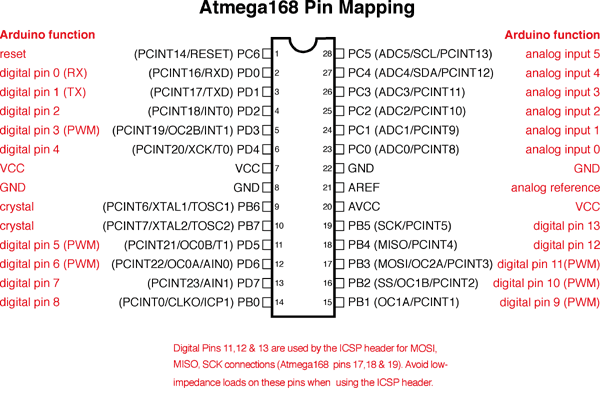
Wire up the ISP and 328p just like we did in ‘Part 0’. Since we don’t have Uno board anymore, you will have to refer to actual Arduino pin mapping. I have also connected an LED with a 220ohm resistor.

Wiring connections
ISP to 328p
D10 –> Pin 1
D11 –> Pin 17
D12 –> Pin 18
D13 –> Pin 19
5V –> Pin 7
GND –> Pin 8
Also, turn on the verbose output from File > Preferences. This will allow us to see what’s going on under the hood.
To upload the blink sketch to our 328p, we cannot just click upload on the IDE. That will upload it to your Nano (ISP) and overwrite ArduinoISP sketch.
Instead, go to Tools > Programmer > choose ‘Arduino as ISP’, and then Sketch > ‘Upload using Programmer’. This will upload the sketch to the ATMega328 using our programmer.
Once it is done, the LED should be blinking.
But wait a second, our LED is blinking but so is LED on the ISP. Well, this is because onboard LED on ISP is connected to D13 and we have it connected to the equivalent pin on 328p. You can disconnect all the connections between them and LED should still blink.
Ditching the Arduino Libraries
The code for the blink.ino looks like this:
    // the setup function runs once when you press reset or power the board
    void setup() {
        // initialize digital pin LED_BUILTIN as an output.
        pinMode(LED_BUILTIN, OUTPUT);
    }

    // the loop function runs over and over again forever
    void loop() {
        digitalWrite(LED_BUILTIN, HIGH);   // turn the LED on (HIGH is the voltage level)
        delay(1000);                       // wait for a second
        digitalWrite(LED_BUILTIN, LOW);    // turn the LED off by making the voltage LOW
        delay(1000);                       // wait for a second
    }
Rewriting this in C.
    int main()
    {
        // One time stuff
        while(1)
        {
            // Loop over and over
        }
    }
We have our main() and an infinite while loop which serves the same purpose as setup() and loop().
Let’s tackle pinMode() and digitalWrite() now.
IO Pins and Registers
Chapter 14 of the datasheet describes how to access I/O Ports. I will summarize it here briefly.
Each I/O pin belongs to one of three ports called PORTB, PORTC, and PORTD.
Each port has three Registers associated with it DDRx, PORTx, and PINx, where ‘x’ is port specifier(B,C, or D).
DDRx Register is to specify Data Direction, we use this to set a pin as INPUT or OUTPUT.
PORTx Register is for setting pins HIGH or LOW.
PINx Register is for reading the pins.
In our case, LED_BUILTIN pin is just Arduino pin D13, which according to the pinout is pin 19 or PB5 (Pin 5 of PORTB).
From the datasheet, we see the following Register descriptions:
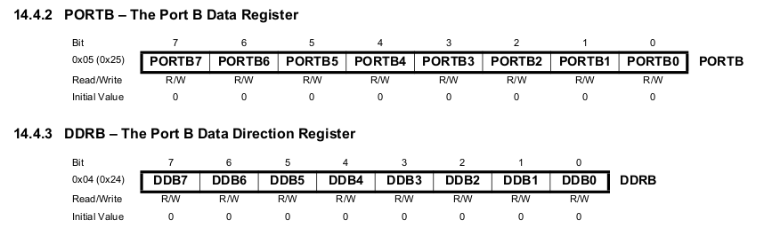
Now we know the memory locations of these registers and bit number of the pin(PB5 is 5th bit).
PORTB is at 0x25
DDRB is at 0x24
Dereferencing pointers
I define PORTB and DDRB Registers by dereferencing their memory locations. I cast the pointer as volatile to tell the compiler that the value of this variable can change outside outside of the program.
#define PORTB *((volatile unsigned char *)0x25)
#define DDRB *((volatile unsigned char *)0x24)
Replace pinMode()
I want to set bit 5 of DDRB to 1 to make it an output. Notice that I cannot just do DDRB = 0b00100000 because that would change the other bits.
To only manipulate one bit I use bitwise OR operator and bit shifting. This method is called bit-flipping.
DDRB |= (1 << 5);
It takes 1, shifts it 5 bits to the left making it 100000 by adding 0s. Then, it performs bitwise OR on DDRB and 100000 which looks like this:
Assume that DDRB = 0bxxxxxxxx
DDRB    0bxxxxxxxx
        0b00100000
OR  =   0bxx1xxxxx
Since this only needs to be done once, it will be outside the while loop.
Replace digitalWrite()
Similarly, to set output pin HIGH, we flip bit on PORTB Register.
digitalWrite(LED_BUILTIN, HIGH) is replaced by PORTB |= (1 << 5)
digitalWrite(LED_BUILTIN, LOW) is replaced by PORTB &= ~(1 << 5)
delay()
This is a tricky one because we don’t have a function in C to count time yet.
AVR has a timer that we can use but to keep things simple, I am going to use an empty for loop.
An empty loop should just waste time to imitate what delay does. However, if there is nothing inside the loop, the compiler catches this and optimizes it. To circumvent that, I will repeat the commands just to fool the compiler.
Final Code
#define PORTB *((volatile unsigned char *)0x25)
#define DDRB *((volatile unsigned char *)0x24)

int main()
{
    // Set pin 5 as OUTPUT
    DDRB |= (1 << 5);

    while(1)
    {
        // Set pin 5 HIGH, LED ON
        PORTB |= (1 << 5);

        // This just wastes time
        for (long i = 0; i < 100000; i++)
        {
            // Need something here to fool the compiler
            PORTB |= (1 << 5);
        }

        // Set pin 5 LOW, LED OFF
        PORTB &= ~(1 << 5);

        for (long i = 0; i < 100000; i++)
        {
            // Need something here to fool the compiler
            PORTB &= ~(1 << 5);
        }
    }
}
Install the toolchain
- As a code editor, I am using Visual Studio Code. It is free and it has a terminal.
- To compile, we will need avr-gcc and some other packages. Run this command to install them.
sudo apt-get install gcc-avr gcc-doc avr-libc - Install AVRdude and its docs
sudo apt install avrdude avrdude-doc
Programming
-
Compiling our blink.c file using gcc-avr is similar to using gcc except that we need to specify our target microcontroller. I got a list of compatible MCUs by running
avr-gcc --target-helpand grepping for “atmega328” and found that the code for our MCU isatmega328p.Let’s compile our blink.c by running:
avr-gcc -mmcu=atmega328 blink.c -o blink.out
This should give us blink.out - To upload this file to our MCU, we will use avrdude. For details about different parameters, check my last post ‘Part 0’.
avrdude -p atmega328p -c stk500v1 -b 19200 -P /dev/ttyUSB0 -v -U flash:w:blink.out:e - Success!!! LED should be blinking now. Congratulations. We have made an LED blink without using Arduino IDE or their libraries and even without using their board.
Note
From what I have read online, it seems that we should not upload the object file (blink.out) directly to the MCU. It must first be converted to a .hex file using avr-objcopy.
avr-objcopy -O ihex blink.out blink.hex
This converts blink.out into blink.hex using output format ihex which stands for Intel Hex.
Interesting to note that the file size is greatly reduced in this conversion.
-rw-rw-r-- 1 saman saman  860 May 21 17:38 blink.hex
-rwxrwxr-x 1 saman saman 6596 May 21 17:27 blink.out
Because we are uploading a .hex file rather than .out, we need to adapt the avrdude command like this:
avrdude -p atmega328p -c stk500v1 -b 19200 -P /dev/ttyUSB0 -v -U flash:w:blink.hex:i
Conclusion
We learned that we can compile and upload a program to MCU with just three commands:
avr-gcc -mmcu=atmega328 blink.c -o blink.out
avr-objcopy -O ihex blink.o blink.hex
avrdude -p atmega328p -c stk500v1 -b 19200 -P /dev/ttyUSB0 -v -U flash:w:blink.hex:i