Making AVR talk with my PC using UART
Objective
Blinking an LED using a microcontroller is one thing. How about making it communicate with other devices? In the simplest case, this means sending ‘Hello, World!’ to my PC.
AVR comes with various peripherals, one of them is an UART.
UART stands for Universal Asynchronous Receiver Transmitter. Asynchronous means that the data is sent without a synchronised clock. This means that the data can be transferred with one less wire.
But the data being sent and received still needs to be synced between devices or they will have no clue how to interpret the bit sequence. To this end, devices needs to agree upon a pre-determined baud rate.
Hardware
My first thought was whether I can hook up the USB cable directly to the microcontroller. After digging a little bit into the USB standard, I learned that it works using something called differential signalling. Connecting D0 and D1 from USB cable to Tx and Rx of UART does not work.
Fortunately, there are USB to TTL cables available on the market for this exact purpose.

For more information about USB protocol, watch this awesome video by Ben Eater.
Wiring
UART uses TXD and RXD pins to transmit and receive data respectively. TXD of one device shall be connected to RXD of the other along with a common ground.
| USB Cable | ATmega328p |
|---|---|
| TXD | RXD |
| RXD | TXD |
| GND | GND |
UART Initialization
As per the datasheet, enabling UART consists of these steps:
1. Setting the Baud rate:
The baud rate is set using UBRRn register, which is split between UBRRnH and UBRRnL.
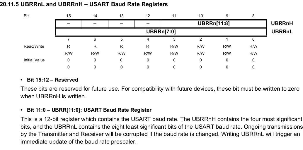
The value to be written to UBRRn for a given baud rate and system clock in Normal mode is calculcated using the following formula.
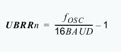
My AVR runs at 8MHz and I plan to use 9600 baudrate which gives me a UBRRn value of 51.
Let’s store it in UBRR0H and UBRR0L (n = 0 because we are using UART0).
UBRR0H = 0;
UBRR0L = 51;
2. Enable Transmitter and Receiver bits
RXENn and TXENn bits in the UCSRnB enable/disable the Receiver and Transmitter respectively.
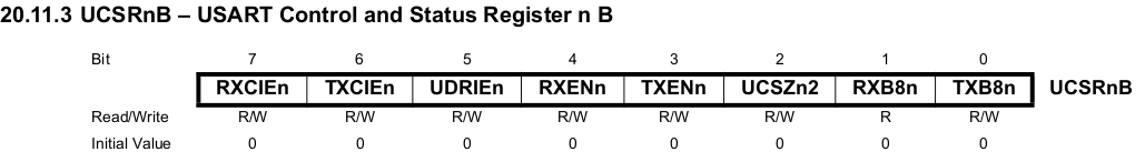
Setting both the bits.
UCSR0B |= (1 << TXEN0) | (1 << RXEN0);
3. Data frame format
Serial data frames are specified by data bits, start bit, stop bits, and parity bits. This is how the receiver differentiates one frame from the other.
In this example, I will use 8 data bits, 1 start bit, 1 stop bit, and no parity bits, just to keep things simple.
Frame format is configured using UCSRnC register.
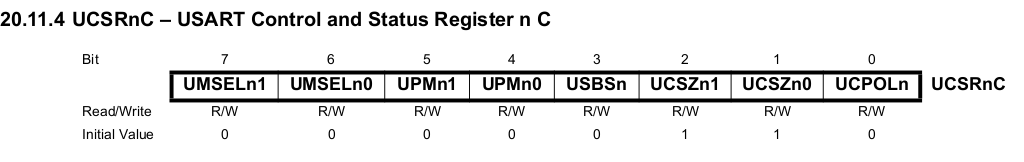 By default, 1 stop bits and no parity bits are used. Therefore, I only need to set bits
 UCSZ00 and UCSZ01 for 8 data bits and we are done.
UCSR0C |= (1 << UCSZ00) | (1 << UCSZ01);
Writing a C program to send ‘Hello, World!’
- I am using
io.hheader file. It contains declarations for the register addresses and pin names so we can work names rather than look up addresses in the datasheet. - I am using
_delay_ms()function fromdelay.hfile. I know this is cheating but I have not implemented by my own delay function using timers. (I should get on top of that soon) - The
printString()function needs some explaining. There are two more registers we should know about,UDRnandUCSRnA.UDRnis the data register where we read/write data that we need to receive/transmit. In the registerUCSRnA, we have a bitUDREnwhich gets set whenUDRnis emptry, i.e. ready for new data.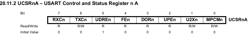
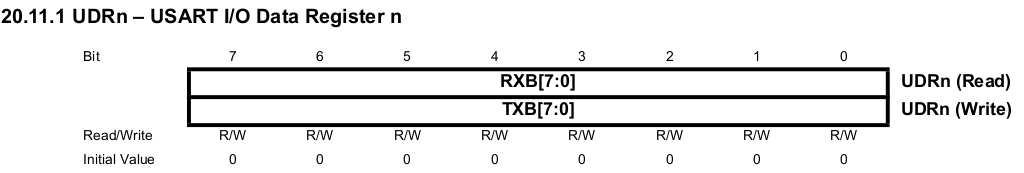
- In a nutshell, we check if the data register
UDR0is empty by checkingUDREnbit. If it is, we put one char from the string into it, rinse, repeat.
Code
    #include <avr/io.h>
    #include <util/delay.h>

    void printString(const char myString[]);

    int main(void) {

        // Set BAUD
        UBRR0H = 0;
        UBRR0L = 51;

        // Set Transmitter/Receiver enable
        UCSR0B |= (1 << TXEN0) | (1 << RXEN0);

        // Set data bits and stop bit
        UCSR0C |= (1 << UCSZ00) | (1 << UCSZ01);

        while(1)
        {
            _delay_ms(1000);
            printString("Hello, World!\r\n");
        }

        return (0);
    }


    void printString(const char myString[])
    {
        int i = 0;
        while (myString[i])
        {
            if (UCSR0A & (1 << UDRE0))
            {
                UDR0 = myString[i];
                i++;
            }
        }
    }
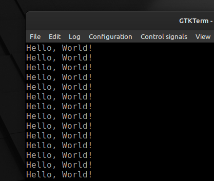
Result
I used GTKTerm as a serial terminal and set it up with the same baud rate, data bits, stop bits, etc.