Sensing temperature using Analog to Digital Converter
Objective
There are more things in heaven and earth, Horatio,
Than are dreamt of in your philosophy.
- William Shakespeare, Hamlet
Very few things in nature are binary. Most of the measurements that interest us are analog. Therefore, the next logical step in my microcontrollers journey is learning how to read analog data.
We will use a temperature sensor which outputs voltage, measure it with the microcontroller, and display that value on my PC using UART over USB.
Background
The AVR we are using is an ATmega328p that has a 10-bit Analog to Digital Converters (ADC).
It maps the analog input to a number in the range [0, 1023] (2^10 values).
ADC works by the method of successive approximation. Consider the schematic below:
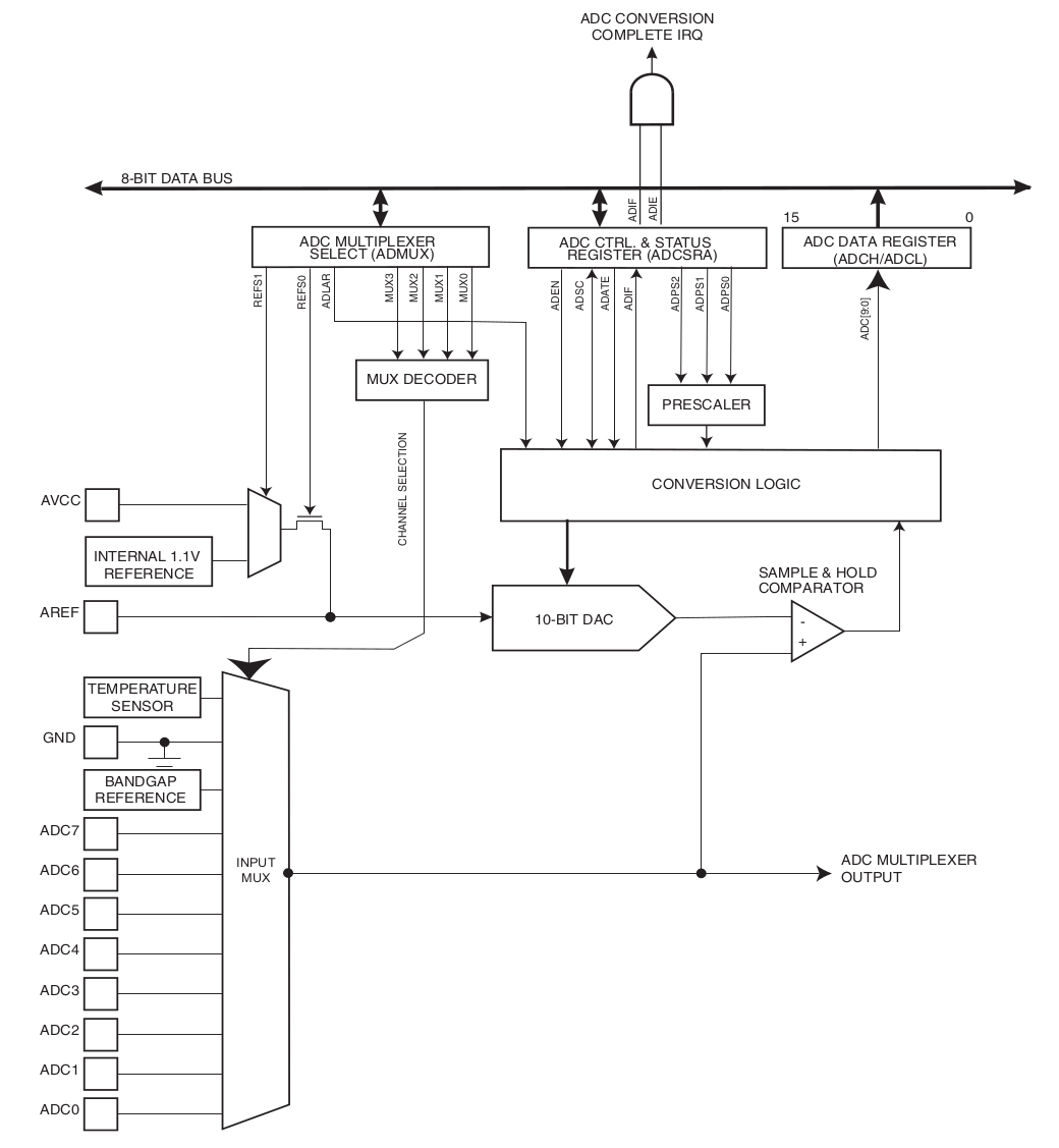
ADC actually consists of a Digital to Analog Converter (DAC) as shown in the schematic.
AREF is the reference voltage and it is the top limit of voltage that can be measured.
The bottom limit is 0 (GND) resulting in the measurement range of 0 to AREF.
ADC0, ADC1, and so on are the analog channels to connect the input.
ADC starts with MSB set to digital 1 as an initial approximation, DAC converts it to analog which is approximately x = AREF/2, and
then comparing it to the input using a Comparator.
If input is higher than x, MSB remains 1, and the next approximation is
(0.5 * AREF + AREF) / 2 = 0.75 * AREF
If input is lower than x, MSB is cleared, and the next approximation is
0.25 * AREF
This process goes on until all the DAC output values corresponding to the 10-bits have been compared to the input.
Let’s take an example using a 4-bit ADC supplied with 4.0V input, 5V being the reference voltage making the range of measurement 0-5V.
Starting with MSB as 1 (0b10000 = 8), the analog equivalent would be (8/16) * 5 = 2.5V.
Input > 2.5, this bit remains set.
Starting with next MSB as 1 (0b1100 = 12), the analog equivlanet would be (12/16) * 5 = 3.75.
Input > 3.75, this bit remains set.
Starting with next MSB as 1 (0b1110 = 14), the analog equivlanet would be (14/16) * 5 = 4.375.
Input < 4.375, this bit is cleared.
Starting with LSB as 1 (0b1101 = 13), the analog equivlanet would be (13/16) * 5 = 4.0625.
Input < 4.0625, this bit is cleared.
As a result, ADC output would be 3.75V corresponding to 0b1100.
The following graphic from Wikipedia provides an excellent visualisation of the process:
 Uwezi, CC BY-SA 4.0 https://creativecommons.org/licenses/by-sa/4.0, via Wikimedia Commons
Hardware
TMP36 is a temperature sensor that outputs a voltage directly proportional to the temperature.
Temperature (°C) = (Vout (V) - 0.5) * 100
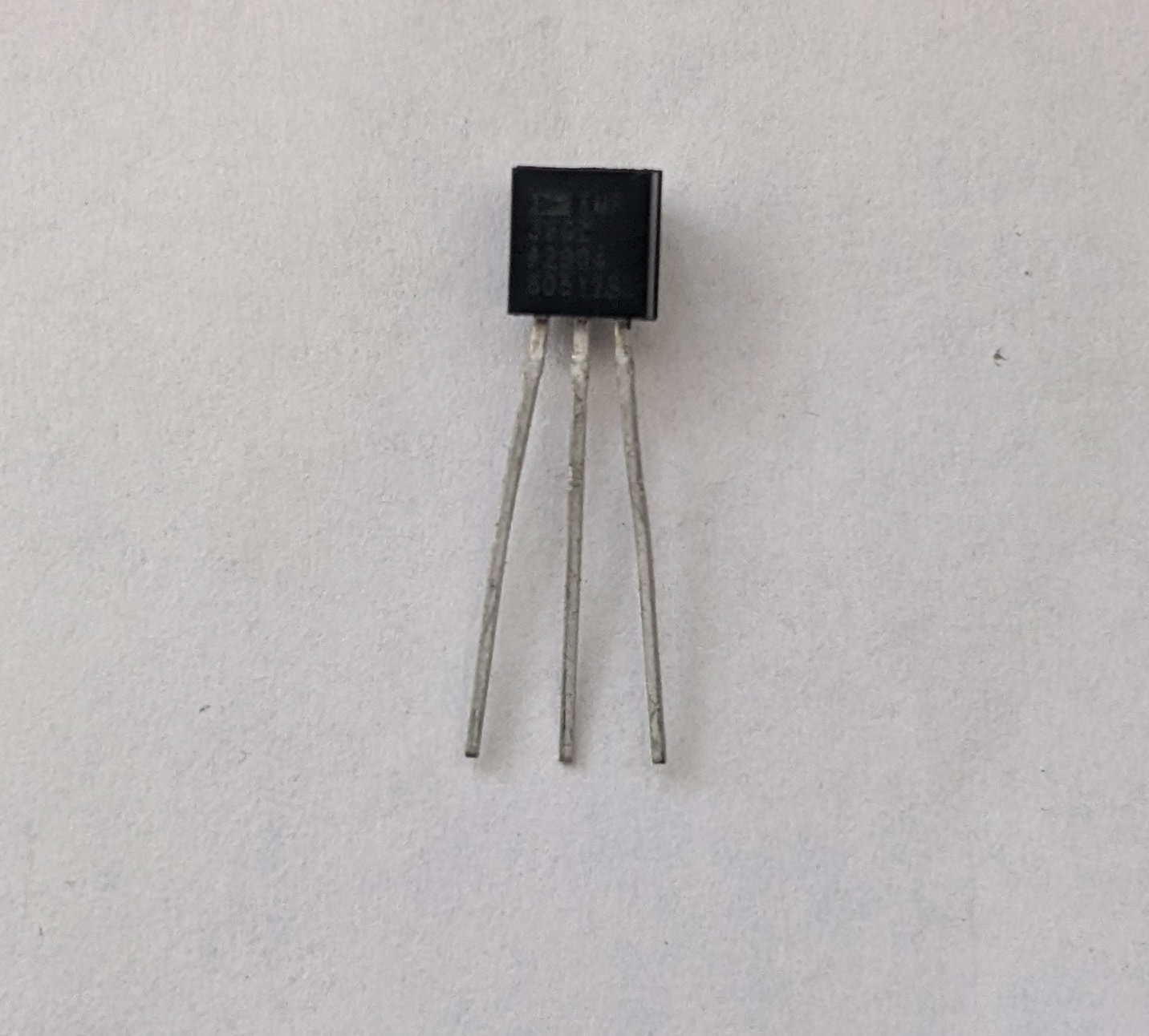
It has three pins 1-3 from left to right when looking at the flat face.
Pin 1 : Vin (Input voltage)
Pin 2 : Vout (Output voltage, to be measured)
Pin 3 : GND
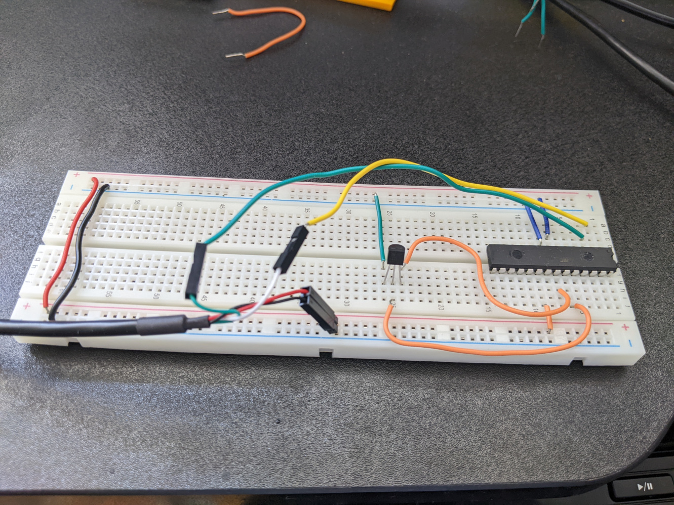
Wiring
In addition to the wiring for UART, we need to make the following connections:
- ADC needs it own power supply on pin 20 (AVCC)
- Pin 1 of TMP36 —> 5V supply
- Pin 3 of TMP36 —> pin 23 (ADC0, analog channel 0)
- Pin 2 of TMP36 —> pin 22 (ADC GND)
ADC Initialization
As per the datasheet, initializing the ADC consists of these steps:
1. Enable ADC
Writing one to ADEN bit of ADCSRA register enables the ADC.
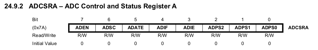
ADCSRA |= 1 << ADEN;
2. Set prescalar
As per the datasheet, ADC successive approximation circuitry requires an input clock frequency between 50kHz and 200kHz.
This means that we need to scale down our microprocessor’s 8MHz clock using a prescalar.
We can select an appropriate prescalar using ADPS0, ADPS1, ADPS2 bits in ADCSRA register as per the following table:
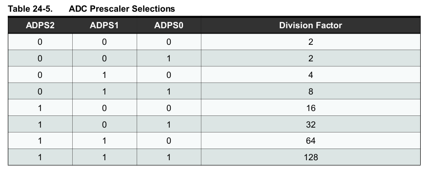
We will set bits ADPS2 and ADPS1 which gives a prescalar of 64 and clock frequency of 8000000/64 = 125kHz
ADCSRA |= (1 << ADPS2) | (1 << ADPS1);
3. Set voltage reference
The reference voltage Vref can be set to either AVCC, internal 1.1V or external using AREF pin
by setting REFS0 and REFS1 bits in the ADMUX register.
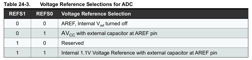
We are using Vref = AVCC in this example.
ADMUX |= 1 << REFS0;
4. Selecting analog channel to use
MUX3…0 bits in ADMUX register are used to select the analog channel.
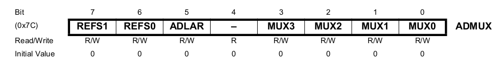
The default value for these bits is 0, which selects ADC0 channel corresponding to pin 23 on the AVR.
5. Reading converted data
The converted data is stored in two registers ADCH and ADCL. Datasheet states that ADCL shall be read before reading ADCH.
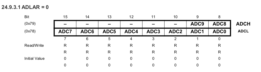
By default, these registers are right-adjusted, meaning ADCH is padded with 0s on the left. To read them together, we left shift ADCH by 8 bits and perform a bitwise OR with ADCL.
adcReading = ADCL | (ADCH << 8);
Code
init_UART()andprintString()functions are same as my UART article- In the
main(), we initialised the ADC as discussed earlier - We declare variables to store the data read from ADC and calculate temperature
- In the while loop, we check if
ADSCbit in theADCSRAregister is cleared. This bit is set to start the conversion. When the conversion is complete, it is cleared by the hardware - If the bit cleared, we read the converted data from the
ADCregister - Because ADC outputs a number in the range
[0, 1023], we have to linearly map it to0-5.0V - Then, we calculate the temperature from the voltage
- Because the
printString()only accepts char arrays, we usesprintf() sprintf()function in avrlib does not support floating points. We separate the temp into two integers to store integral and decimal part.
#include <stdio.h>

#include <avr/io.h>

#include <util/delay.h>

void init_UART() {
  // Set BAUD
  UBRR0H |= 0;
  UBRR0L |= 51;

  // Set Transmitter/Receiver enable
  UCSR0B |= (1 << TXEN0) | (1 << RXEN0);

  // Set data bits and stop bit
  UCSR0C |= (1 << UCSZ00) | (1 << UCSZ01);
}

void printString(const char myString[]) {
  int i = 0;
  while (myString[i]) {
    if (UCSR0A & (1 << UDRE0)) {
      UDR0 = myString[i];
      i++;
    }
  }
}

int main(void) {

  init_UART();

  // Enable ADC and set prescalar
  ADCSRA |= (1 << ADEN) | (1 << ADPS2) | (1 << ADPS1);

  // Set reference
  ADMUX |= 1 << REFS0;

  int adcReading = 0;
  char serialOutput[8];
  double temp = 0;

  while (1) {
    if (!(ADCSRA & (1 << ADSC))) {
      adcReading = ADCL | (ADCH << 8);

      // Map to 0-5.0V. This introduces inaccuracies if VCC is not
      // 5.0
      temp = (adcReading / 1024.0) * 5.0;

      // Convert voltage to degrees celcius
      temp = (temp - 0.5) * 100;

      // Calculate integer and decimal part of temp as sprinf() function
      // in avrlib does not support floating point. This is a hacky workaround.
      // Alternative is to link a floating-point library.
      int integer_part = (int) temp;
      int decimal_part = (int)(temp * 10) % integer_part;
      sprintf(serialOutput, "%d.%d\r\n", integer_part, decimal_part);
      printString(serialOutput);

      // Start the conversion
      ADCSRA |= (1 << ADSC);
      _delay_ms(1000);
    }
  }

  return (0);
}
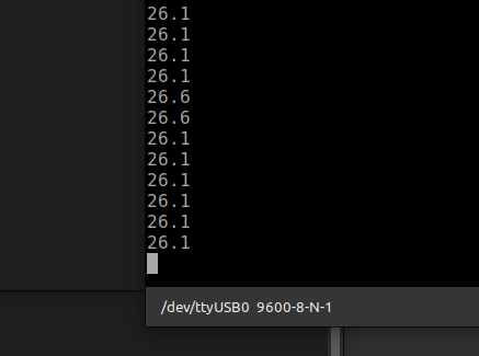
Result